The Hydrogen engine appears with different names like H2 ICE which means Hydrogen Internal Combustion Engine. In some countries the specification would be described as Hydrogen Spark Ignition engine. This post is a quote from the book about alternative fuel from 2020 by Springer.

Hydrogen in Spark Ignition Engines
P. V. Elumalai , N. S. Senthur, M. Parthasarathy , S. K. Das , Olusegun D. Samuel , M. Sreenivasa Reddy , A. Saravana , S. Anjanidevi , Adduri SSM Sitaramamurty , M. Anusha , and Selçuk Sarıkoç
Abstract In the present world, there is a huge demand for spark ignition (SI) hydrogen engines in transportation sector as there is an increase in population of light commercial vehicles such as motorcycles and cars. Petrol powered SI engine produces less noise and vibration with hight hermal efficiency as compared with diesel engines. Utilization of hydrogen as fuel in SI hydrogen engines has found to improve the combustion and performance characteristics of engines. The primary fuel petrol and secondary fuel hydrogen are induced in the inlet manifold. The various percentage of hydrogen used in the SI hydrogen engines include 5, 10, 15, 20 and 25%, together with different ratios of petrol fuel. Whenever hydrogen induced in the SI or compression ignition (CI) engines for safety purpose a flame arrester is used. This current was assessed to calculate the combustion, performance and emission characteristics of a high-speed single cylinder SI engine operating with different hydrogen–petrol blends. The various percentage of hydrogen was inducted along with petrol fuel to reduce the tailpipe emissions.
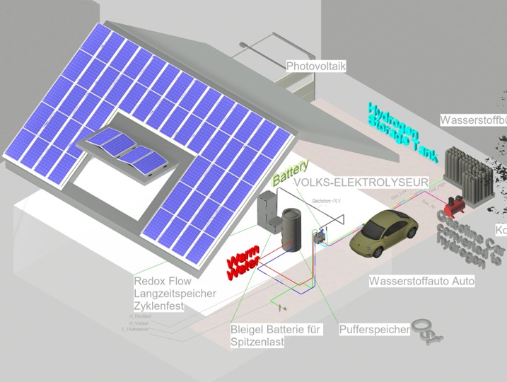
In order to add hydrogen you need an electrolyzer. Read this article to know more about making your own hydrogen fuel for the hydrogen engine.
P. V. Elumalai (B) · S. K. Das · M. Sreenivasa Reddy · A. Saravana · S. Anjanidevi ·
A. SSM Sitaramamurty · M. Anusha
Department of Mechanical Engineering, Aditya Engineering College, Surampalem, India e-mail: elumalai@aec.edu.in
N. S. Senthur
Department of Mechanical Engineering, Bharath Institute of Higher Education and Research, Chennai, India
M. Parthasarathy
Department of Mechanical Engineering, Vel Tech Rangarajan Dr. Sagunthala R&D Institute of Science and Technology, Chennai, India
O. D. Samuel
Department of Mec Hanical Engineering, Federal University of Petroleum Resources, P.M.B 1221, Effurun, Delta State, Nigeria
Department of Mechanical Engineering, Science Campus, University of South Africa, Private Bag
X6, Florida 1709, South Africa
S. Sarıkoç
Department of Motor Vehicles and Transportation Technologies, Amasya University, Tasova Yuksel Akin Vocational School, Amasya, Turkey
© The Author(s), under exclusive license to Springer Nature Singapore Pte Ltd. 2022 195
G. Di Blasio et al. (eds.), Application of Clean Fuels in Combustion Engines, Energy, Environment, and Sustainability, https://doi.org/10.1007/978-981-16-8751-8_10
The hydrogen was mixed with base fuels such as P95H5 (95% petrol, 5% of hydrogen),
P90H10 (90% petrol, 10% of hydrogen), P85H15 (85% petrol, 15% of hydrogen), P80H20(80%petrol,20%ofhydrogen)andP75H25(75%petrol,25%ofhydrogen). About 20% of hydrogen blend showed greater brake thermal efficiency of 26.8% when compared with base fuel. Furthermore, 25% of hydrogen mixed with petrol drastically reduced the hydrocarbon content, carbon monoxide content and exhaust gas temperature petrol by 22.8%, 40.26% and 15.61%, respectively, when compared with base fuel at full load condition.
Keywords Hydrogen · Petrol · Hydrocarbon · Brake thermal efficiency ·
Carbonmonoxide
10.1 Introduction to the hydrogen engine
The fossil fuel powered industries are under immense pressure to meet the required strict emission targets. Fossil fuel shortages and environmental pollution demand some cleaner and sustainable fuel that can dominate both the power and internal combustion hydrogen engine industry (Brayek et al. 2019). Hydrogen and fuel cells have the potential to minimise greenhouse gas emissions in a variety of applications due to their high efficiency and near-zero emission operations. According to a study financed by the Energy Department, hydrogen has the potential to reduce emissions in the following ways: (a) in light-duty highway vehicles, emission reduction is more than 50% to 90%, compared with today’s petrol vehicles; and (b) in specialty vehicles, emissions are reduced by more than 35%, compared with contemporary diesel and battery-powered lift trucks; and (c) transit buses have shown to be 1.5 times more fuel efficient than diesel fuelled internal combustion engine buses and 2 times more efficient than natural gas powered buses. Auxiliary power units (APUs) reduce pollutants by more than 60% when compared with idling truck engines. Combined heat and power (CHP) systems reduce emissions by 35–50% when compared with traditional heat and power sources (Changwei and Wang 2009). The most difficult aspect of producing hydrogen, especially from renewable sources mainly depends on the investment. On a per-mile basis, the hydrogen engine must be cost-competitive with conventional fuels and technology for use as transportation fuel cells. Another challenge is the storage of hydrogen as it is highly flammable. Apart from being a clean burning fuel having superior physico-chemical properties, hydrogen has already established its space in energy sector (Changwei et al. 2010). Hydrogen can be produced from a range of local sources, including natural gas, nuclear power, biomass, and renewable energy sources such as solar and wind power. These characteristics make it a desirable fuel for transportation and electricity generation. It can be readily utilized in automobiles, homes, portable powers, and a variety of other applications. Natural gas is now the most common source of hydrogen generation, accounting for roughly three-quarters of the total dedicated hydrogen production of around 70 million tons per year. This accounts for around 6% of global natural gas consumption (Das 2007). In comparison to typical fossil fuels like petrol, diesel, and natural gas, hydrogen has a wider range of combustion parameters like faster diffusion rate and flame propagation (Dash et al. 2020). Hydrogen also possesses quite low ignition energy. Because of a variety of factors, hydrogen has recently gained momentum as a viable energy resource for upcoming generation of automotive. In addition to hydrogen atoms, all common fossil fuels contain carbon atoms and moreover carbon dioxide (CO2) is a major product generated during the conversion of the fuel to energy. The hydrogen releases just water as a by-product but not CO2 which is a major greenhouse gas. However, pure hydrogen suffers storing issues which can be addressed by blending with other liquid fuels. Production, storage, portability, transport, and purity are the main drawbacks that prevent hydrogen from becoming a widely used engine fuel (Edmondson and Heap 1971). Over a wide spectrum of air–fuel ratio, hydrogen can be utilized in IC engines. Over many decades, several researchers have attempted to use hydrogen as an engine fuel with varying levels of success. Several successful projects have proved that hydrogen is far superior to present automotive fuels in many ways. Elkelawy and Bastawissi 2013 studied the inclusion of hydrogen to a petrol powered spark ignition engine at various operating regime. They observed that the engine’s idle speed is roughly maintained around its initial objective as hydrogen enrichment levels rise, while spark timing varies somewhat with and without hydrogen addition. With hydrogen, however, the intake air flow reduces. The SI engine with hydrogen enrichment has a higher indicated thermal efficiency. The periods of flame generation and propagation, as well as COVimep, decrease as the proportion of hydrogen infusion is increased. They also reasoned that with the decreased in-cylinder temperature and increased residual gas percentage, NOx emission reduces as hydrogen enrichment increases. CO and HC emissions initially fall with the addition of hydrogen but when the hydrogen energy share hits 14.44% the emission begin to rise again. Shivaprasad et al. (2014) experimentally studied the performance of a high speed Lombardini make 9 kW@4400 rpm petrol engine with the inclusion of hydrogen share from 0–25 vol.%. Hydrogen addition resulted in improved brake mean effective pressure. Furthermore, 20% hydrogen inclusion results in maximum BMEP at engine speed of 3000 rpm. They also witnessed a rise in BTE up to 20% hydrogen share. By hydrogen enrichment, reduction in CO and HC emission is seen, whereas, rise in NOx emission is also seen. Elumalai et al. 2021 observed that for direct injection hydrogen powered SI Hydrogen engine the performance is improved at partial loads. Technically, no CO2 emission is reported and minor HC and CO forms as a result of engine oil burning inside the cylinder, however, NOx emission increased considerably for λ value of 1 to 2 (9). Studied the performance of a four cylinder water cooled engine powered by mixture of petrol and hydrogen, where hydrogen is added by direct injection. They employed unique lean burn technology for the engine trial. The oxygen content in the combustion system is increased due to the lean burn. Additionally, hydrogen has a faster flame propagation rate, which may aid in CO oxidation. After infusing 10% share of hydrogen, the mean effective pressure and thermal efficiency are enhanced by 10% and 4–4.5%, respectively.Althoughleanburncanenhancethermalefficiencyandreducethrottling loss, it increases COV and HC emissions. With an acceptable injection technique and lean burn circumstances, the COV can be lowered to below 1% and HC emission can be identical to the standard objective level. The inclusion of hydrogen raises the peak cylinder warmth, resulting in a considerable rise in NOx emissions; however, using lean-burn technology, NOx can be dramatically reduced while power and fuel efficiency can be significantly improved. Ji and Wang 2009 studied the hydrogen powered Hydrogen engine characteristics with ECU operated time-based manifold injection system. All experiments are conducted at speeds ranging from 1100 to 1800 rpm. For comparison purposes, baseline observations are made with petrol. In the event of hydrogen operation, maximum braking power is reduced by 19.06%, while peak brake thermal efficiency is raised by 3.16%. They reasoned that due to lower volumetric efficiency of hydrogen, the brake power is lowered. Karim 2003 have made numerical investigation to optimize the various injection strategies, such as port fuel injection (PFI), direct injection (DI) and combination of PFI + DI, on the hydrogen fuelled SI engine characteristics. At wide-open throttle, the suggested hybrid techniquecansatisfylowandhighloadsituationswithoutanomalouscombustion.Atlow and high load areas, the hybrid approach of PFI + DI has higher suggested thermal efficiency and engine operation consistency than port fuel injection and in-cylinder direct injection, respectively. From the literatures, it was observed that limited works have been reported on hydrogen powered SI hydrogen engine. Moreover, some results are also contradictory with respect to NOx and HC emissions. In this backdrop, much quality based work needed to be done on hydrogen powered SI engines in order to draw some strong conclusions and plan future prospects.
In Table 10.1 two symbols are used the upward triangle shows an increase and downward triangle shows a decrease. NC means no change.
Table 10.1 Performance and emissions characteristics of SI engines fuelled by hydrogen
H2 Supply | Load (%) | Performance | Emission Characteristics | References | ||||
BSFC | BTE | CO | NOx | HC | PM/Smoke | |||
9.4–37% | 25–100 | NC | ▲ | ▼ | ▼ | ▲ | ▼ | Li and Karim (2006) |
9.4–37% | 50–75 | NC | ▲ | ▼ | ▲ | ▲ | ▼ | |
2–9.5 lpm | 25 | NC | ▲ | NC | ▼ | ▼ | ▼ | Masood et al. (2007) |
2–9.5 lpm | 50–75 | NC | ▲ | ▲ | ▲ | ▲ | ▼ | |
2–9.5 lpm | 100 | NC | ▲ | ▲ | ▼ | ▼ | ▼ | |
10–40% | 10 | ▲ | ▼ | ▼ | ▼ | ▼ | ▼ | Murugesan P et al. (2017) |
10–40% | 30 | ▲ | ▼ | ▼ | ▼ | ▼ | ▼ | |
10–40% | 50 | ▼ | ▲ | ▼ | ▼ | NC | ▼ | |
10–40% | 70–90 | ▼ | ▲ | ▼ | ▼ | ▼ | ▼ | |
0–46% | 100 | ▲ | ▲ | ▼ | ▲ | ▲ | ▼ | Navale et al. (2017) |
10–100% | 20–100 | ▼ | ▲ | ▼ | ▲ | ▼ | ▼ | Negurescu et al. (2012) |
0–38.6% | 100 | ▲ | ▲ | ▲ | ▼ | NC | – | Perumal Venkatesan et al. (2021) |
Table 10.2 Comparison of properties of various gases versus hydrogen
Properties | Methane | Propane | Octane | Methanol | Hydrogen |
Density (kg/m3) | 0.656 | 2.009 | 780 | 793 | 0.083 |
LHV (MJ/kg) | 50 | 45.6 | 47.9 | 22.4 | 120 |
Viscosity (10–5 Pas) | 1.03 | 0.43 | 0.53 | 0.61 | 0.84 |
Stoichiometric ratio | 17.2 | 15.6 | 14.7 | 6.5 | 34.3 |
Combustible range (%) | 5–15 | 2.1–9.5 | 0.95–6 | 6.7–36 | 4–75 |
Adiabatic flame temperature (°C) | 1949 | 1980 | 1927 | 1963 | 2254 |
Ignition energy (mJ) | 0.30 | 0.30 | 0.26 | 0.14 | 0.017 |
Ignition temp (°C) | 540–630 | 450 | 415 | 460 | 585 |
10.2 Materials and Methods for hydrogen engine
10.2.1 Hydrogen combustion engine ICE
Hydrogen is a clean-burning fuel when compared with other types of alternative fuels like biofuel, CNG, LPG, and biodiesel. There are various methods to produce hydrogen gas such as steam reforming and electrolysis of water. Now-a-days, many application sectors use hydrogen as an energy source (Rahaman et al. 2009). The use of hydrogen in IC engines is a very lesser quantity because of safety and handling issues. There are many benefits when hydrogen is used as a fuel in an IC engine, the results were obtained have more advantages than conventional fuels inclusive of lesser noise, lower vibration, greater efficiency, and cutdown the emission. Hydrogen is the only gas having greater octane (>130) when compared with other types of gases. Hydrogen has the only demerit of storage and handling when used in an IC engine. And also, a very much less quantity of hydrogen can only be used in the combustion process of an IC engine (Sandalcı and Karagoz 2017). Table 10.2 shows the comparison of properties of various gases versus hydrogen.
10.2.2 Fuel Preparation
The present investigation was analyzed in SI engine powered by hydrogen blend petrol. From the study, primary fuel is used as petrol and secondary fuel is hydrogen. The hydrogen mixed with base fuel was prepared the fuel blend of P95H5 (95% g Petrol, 5% hydrogen), P90H10 (90% petrol, 10% hydrogen), P85H15 (85% g Petrol, 15% hydrogen), P80H20 (80% g Petrol, 20% hydrogen), and P75H25 (75% g Petrol, 25% hydrogen) as shown in Fig. 10.1.
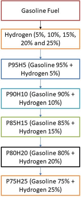 Fig. 10.1 Flowchart depicting concentration of fuel used in analysis
10.3 Experimental Setup
The experiment was carried on single cylinder PRODIT petrol engine. Table 10.1 provides details of engine. The research lab consisted of test rig including an eddy current-type dynamometer, exhaust gas analyzer, petrol metering device as well as other auxiliary equipment (Saravanan and Nagarajan 2009a). A diagrammatic representation of the test rig is given in Fig. 10.2. A 50 kg hydrogen cylinder was used to supply hydrogen in the intake manifold. Cylinder contains compressed hydrogen at 200 bar. The hydrogen stream regulate framework had been fitted at the upper corner of the hydrogen cylinder that consisted of hydrogen controller as well as the hydrogen flow pointer. The hydrogen control process controls the hydrogen stream supplied to the engine as well as the quantity of hydrogen stream could be defined by hydrogen stream pointer(ChangweiandWang2009).The petrol engine was modified for utilizing hydrogen along with gasoline. The flame trap placed was placed in the middle of the hydrogen cylinder and engine which is used to suppress the back fire in
Fig.10.3.Thepreparedelectroniccontrollerwasconnectedwiththedataprocessorto

Fig. 10.2 Experimental setup
the RS-232 port. The exhaust release from the test engine had been assessed utilizing exhaust gas analysis apparatus that was located at exhaust system. An assessment of sensor performance, including ranges, cross sensitivity, reliability, durability, and expense are made. As hydrogen leakage are probable, hydrogen sensors are installed at hydrogen connectors that are regularly isolated, where hydrogen may concentrate in buildings air inlet and outflow pipes. While developing a hydrogen detection technique, aspects such as sensor reaction times, detection limit, sensor serviceability, sensor maintenance and calibration needed, issues arising due to sensitivity, and field of view should be considered. Special attention must be paid to the identification of hydrogen leaks and hydrogen flame in hydrogen test cells. Apart from detecting gaseous hydrogen to ensure a safe test cell atmosphere, hydrogen leakage should also be monitored as leakage could easily produce flames without warning. Especially, a hydrogen leakage would not be easily detected using a gaseous hydrogen monitoring device until it leads to ignition. The experiment assessed at engine speeds of 2000–4000 rpm by incrementing the speed around 500 rpm. Using a controller, the various mass fraction of hydrogen (5, 10, 15, 20, and 25%) was inducted along with base fuel. The present study intended to analyze the operation as well as release of toxic gas attributes in a high velocity SI engine that had utilized hydrogen enhanced besides ECU regulated MPI system. Table 10.3 shows that specification of engine.

Fig. 10.3 Graph depicting speed versus BTE
Table 10.3 Engine specification
Engine model | PRODIT Gpetrol engine |
Bore (mm) | 90 |
Stroke (mm) | 85 |
Compression ratio | 9.6 |
Maximum torque | 23 Nm |
Maximum power | 11 kW |
Ignition timing | 9.10 CA before TDC |
Fuel | Petrol fuel hydrogen |
+
10.3.1 Uncertainty Analysis
The results of the analyses performed using various apparatus largely depend on the standard of the manufacturers. To overcome the drawbacks and to assure standard results using the instruments, uncertainty analyses of various systematic parameters are performed. Errors and uncertainty while using instruments largely depend on various natural conditions, perceptions, assembling of the instruments, working conditions, and also on the accuracy of the instruments. The evaluation tests were performed four times and the average values were taken for the assurance of vulnerability in this work as shown in Table 10.4.
S. no | Parameters | Systematic errors (±) |
1 | Load indicator | 0.2 |
2 | Speed sensor | 1.0 |
3 | Temperature sensor | 0.1 |
4 | Pressure sensor | 0.5 |
5 | Crank angle encoder | 0.2 |
6 | Smoke meter | 1.0 |
8 | Fuel burette | 1.0 |
9 | Manometer | 1.0 |
Table 10.4 Uncertainty analysis
![]() [uncertaintyofload]2+[uncertaintyof speed]2+[uncertaintyof Temp]2+ [uncertaintyof unburntPressure]2+[uncertaintyof CA]2+
[uncertaintyofload]2+[uncertaintyof speed]2+[uncertaintyof Temp]2+ [uncertaintyof unburntPressure]2+[uncertaintyof CA]2+
![]() [uncertaintyof smoke]2+[uncertaintyof f uel]2+
[uncertaintyof smoke]2+[uncertaintyof f uel]2+
[uncertaintyof manometer]2

= 2.21%
10.4 Results and Discussion about the hydrogen engine
The two fuels used in the SI hydrogen engine include the primary fuel petrol and the secondary fuel hydrogen. The hydrogen mixed with base fuels were P95H5 (95% petrol, 5% hydrogen), P90H10 (90% petrol, 10% hydrogen), P85H15 (85% petrol, 15% hydrogen engine), P80H20 (80% petrol, 20% hydrogen), and P75H25 (75% petrol, 25% hydrogen). The various concentrations of hydrogen and petrol fuels filled with SI engine were found performance and emission characteristics.
10.4.1 Brake Thermal Efficiency of hydrogen engine
Figure 10.3 expose the variations of brake thermal efficiency (BTE) and different speed conditions of SI engine. The BTE evaluates the performance of the engine. The induction rate of hydrogen was increased with increase in the BTE of engine for all load conditions. petrolIt was clearly observed that the highest BTE was 26.05% for P80H20 at speed 3500 rpm. It might be due to premixed charge of hydrogen and petrol and high energy density of hydrogen which exhibits better oxidation process (Saravanan and Nagarajan 2009b). The BTE of P95H5, P90H10, P85H15, P80H20, and P7525 is 20.1%%, 22.3%, 23.0%, 25.0%, and 22 0.06%, respectively, when compared with 17.6% for without hydrogen induced P100. It could be attributed that the flame speed of hydrogen is three times greater than the petrol and wide range of flammabilityofhydrogenwhichscatteredthroughoutthechambercanbeachievedby complete combustion petrol. The petrol mixture blended with hydrogen showed faster combustion and enriched energy value thus resulting in better combustion efficiency. The results also showed that BTE of 0% hydrogen induction showed lower BTE than other test fuel condition due to energy value of petrol premixed charge was lower than hydrogen premixed charge. Moreover, 20% hydrogen enrichment was exhibited 14.4, 10.5, 5.6 and 5.4% higher BTE P95H5, P90H10, P85H15 and P75H25 at rated speed condition. Addition of hydrogen above 20% to the petrol fuel showed decrease in BTE, due to the irregular flame propagation and start of combustion which leads to notice the unstable engine operation. Saravanan et al. 2007 as the fraction of hydrogen added increases accumulation of hydrogen increases in the cylinder which results in a decrease in the amount of air required for complete combustion. For these reason, the 25% hydrogen enrichment fuel was found to have low thermal efficiency (Satyapal 2017).
10.4.2 Brake Mean Effective Pressure
Figure 10.4 exhibits the difference of brake mean effective pressure (BMEP) for the hydrogen enrichment petrol in SI engine. In Fig. 10.4, it was clearly seen that gradual increase in hydrogen concentration in the fuel mixture gradually increases the BMEP all speed condition. Due to greater value of octane number and wider range of flammable limits found in the hydrogen fuel, the combustion pressure also increases the BMEP. In addition, the hydrogen has faster flame propagation and greater adiabatic temperature when compared with the petrol fuel that are helpful for uniform combustion throughout the chamber. By increasing the hydrogen concentration by 25%, the BMEP was decreased by 4.5% when compared with P80H20. Combination of multi-directional flame propagation and less entry of air into the manifold leads to inferior combustion rate. The P80H20 showed higher value of BMEP when compared with the other test fuels. It might be due to unidirectional flame propagation and less flame quenching zones leading to better combustion rate thereby enhanced BMEP (Shivaprasad et al. 2014).
10.4.3 Carbon Monoxide
Figure 10.5 displays graph depicting the difference in carbon monoxide (CO) with various engine speed condition for petrol enriched hydrogen. Normally, petrol operatedSIengineemitsmoreCOathigherspeedconditionduetopoorairutilizationand fuel rich zone in chamber petrol. The test results showed that a reasonable reduction of CO emission was found in the hydrogen enriched SI engine. It was mainly due to

Fig. 10.4 Graph depicting speed versus BMEP

Fig. 10.5 Graph depicting speed versus CO
the absence of carbon atoms in the hydrogen fuel leading to restriction of CO formation (Shivaprasad et al. 2014). When increasing the hydrogen concentration with the petrol, the drastic reduction of CO emission was observed whereas beyond 25% hydrogen enrichment the CO emissions start to increase. This result increases the wall impingement and enhances the ignition lag that results in incomplete combustion. The magnitude of CO emission for the fuels P95H5, P90H10, P85H15, P80H20, and P75H25 were reduced by 8.8%, 14%, 31.3%, 33.5%, and 41.2%, respectively, when comparedwithP100.ItcanbeinferredthatmorechancesforformationofOHradical by hydrogen enrichment can results in better combustion efficiency. Utilization of hydrogen along with petrol leads to positive impact on greater flame velocity, faster combustion rate, and higher stoichiometric air–fuel ratio that results in improve the CO oxidation. The 25% of hydrogen induction showed 26.2%, 13.5%, 9.8% and 4.7% lower CO emission than hydrogen induction of 5, 10, 15, and 20% respectively. The hydrogen produces higher combustion temperature when compared with the petrol which aids to enhance the carbon oxidation. The maximum CO reduction was achieved by 25% of hydrogen induction because of high adiabatic flame temperature and wide flammability which enhance the CO conversion rate into CO2. While increase in the hydrogen induction beyond 25% leads to replacement of air quantity that results in poor air utilization and lower volumetric efficiency therefore reduced CO2 formation.
10.4.4 Hydrocarbon
Figure10.6 exhibits the difference in hydrocarbon (HC) emission with respect to variable engine speed for hydrogen enrichment with P100. From the results, it can be seen that petrol powered SI engine produced higher HC emission than hydrogen assisted combustion of petrol. When increasing the hydrogen concentration, the HC emission was drastically reduced at all speed condition. It could be ascribed that addition of hydrogen and formation of OH radial in to the combustion process enhances the oxidation of fuel. The test results also revealed that the premixed charge of hydrogen and petrol were found to minimize HC emission because of high post-combustion temperature and enhanced oxidation reaction which promoted faster combustion rate. The other possibility to reduce the HC emission for hydrogen induction was by lowering the quenching distance and high flame velocity those results in shortening the combustion duration (Shivaprasad 2018).
The shortening of quenching distance and combustion duration helps to burns the fuel completely during combustion which in turn reduces HC formation. The HC emission for P95H5, P90H10, P85H15, P80H20, and P8025 was reduced by 6.7%, 9.8%, 11.6%, 19.7%, and 22.8%, respectively, when compared with the P100. The P100 found highest HC emission of about 224 ppm. It was mainly due to the lesser chemically correct mixture of petrol which enabled more amount of fuel to enter

Fig. 10.6 Graph depicting speed versus HC
into the chamber and inferior air utilization also results in HC formation. The 25% of hydrogen induction drastically reduced the HC emission as related to P100. It might be due to high stoichiometric air–fuel mixture of hydrogen (34:1) and high diffusivitywithairthatresultsinmoreairutilizationandpromotetheinitialoxidation of hydrocarbon.
10.4.5 Oxides of Nitrogen (NOx) of the hydrogen engine
The effect of hydrogen enrichment with P100 on formation of NOx emission in SI engine is portrayed in Fig. 10.7. Evolution of higher temperature during combustion results in NOx formation in the engine. While increasing the concentration of hydrogen gradually increase the NOx emission in SI engine. It could be attributed to higher heat value of hydrogen dissipate more amount of heat during combustion that aids to promote the nitrogen oxidation (Soberanis and Fernandez 2010). In addition, higher hydrogen induced in to the inlet manifold raises the combustion rate which enhances the post-combustion temperature. The NOx emission for P95H5, P90H10, P85H15, P80H20, and P8025was increased by 11.3%, 21%, 40.6%,55%, and 62.3%, respectively, when compared with P100. The 25% of hydrogen induced in to the base fuel showed the maximum rate of formation of oxides of nitrogen at rated speed
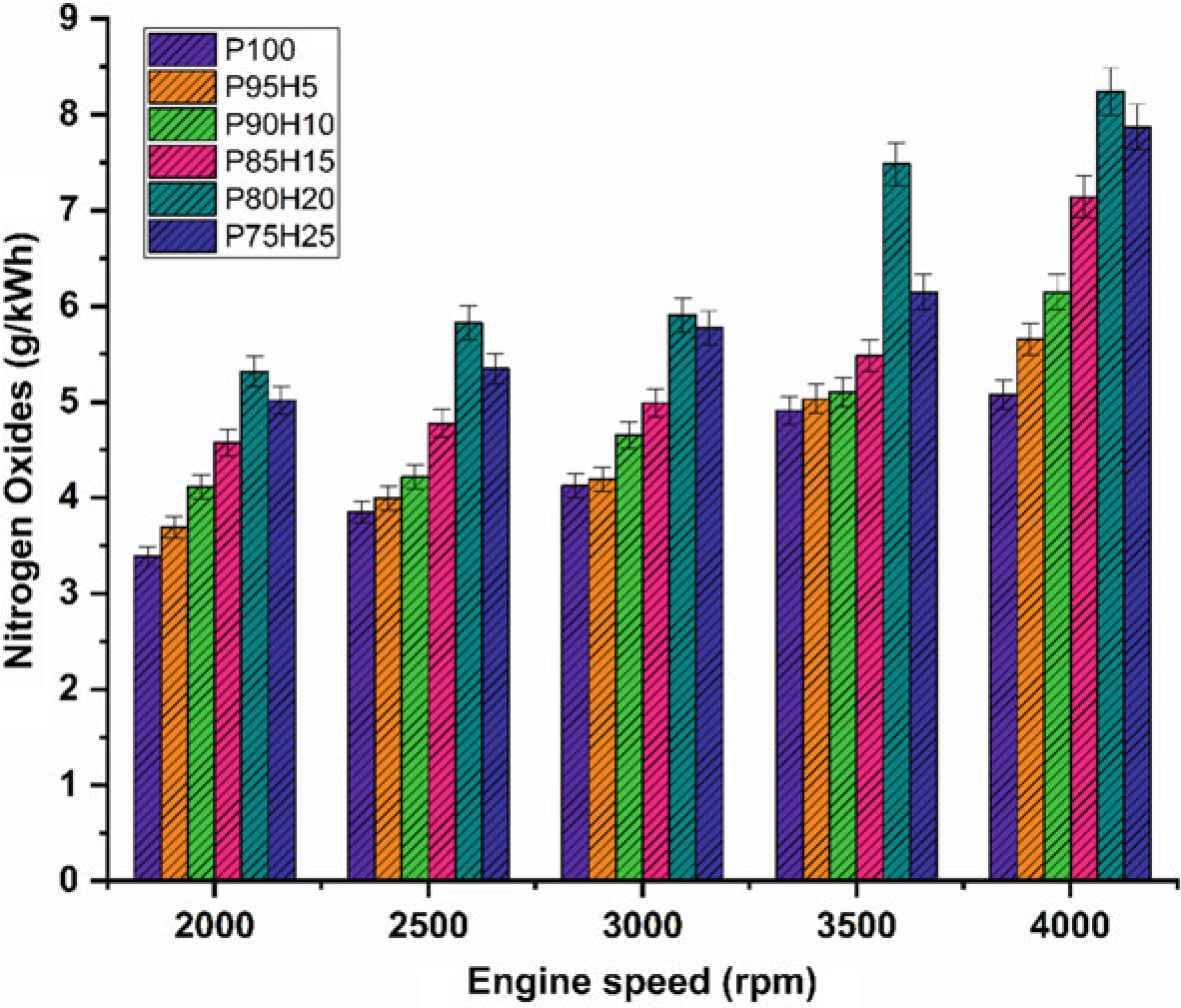
Fig. 10.7 Graph depicting speed versus NOx
condition. This was mainly due to the wide flammability and high cylinder temperature produced during combustion which exhibited more NOx formation (Verhelst and Wallner 2009). The lowest oxides of nitrogen are observed for blend P100 which was18.2%lowerwhencomparedwith25%of hydrogen induced fuel. This result was responsible for lower heating value and less air–fuel ratio of P100 which results in fuel rich zone in cylinder therefore lower combustion temperature (Verhelst et al. 2006).
10.4.6 Exhaust Gas Temperature
The impact of hydrogen enrichment with P100 on exhaust gas temperature (EGT) in SI engine was represented in Fig.10.8. The shorter combustion rate and high cylinder temperature leads to production of higher EGT. It was evident that hydrogen enriched fuel observed higher EGT than normal fuel because of high adiabatic flame temperature of hydrogen which resulted in enhanced post-combustion temperature. EGT for all test fuels was lower under low speed condition. At full speed condition, high rate hydrogen induction with base fuel produced superior EGT than lower rate of hydrogen induction. It was mainly due to more air utilization and better combustion leading to rise in cylinder temperature (White et al. 2006). When increasing the hydrogen concentration linearly the EGT increases for all speed condition. The

Fig. 10.8 Graph depicting speed versus EGT
highest EGT was observed for 25% of hydrogen induction owing to a higher diffusivity of hydrogen which leads to easily mix the fuel with air thereby increasing the homogenous charge preparation. The EGT of P95H5, P90H10, P85H15, P80H20, and P75H25 was increased by 4.7%, 8.3%, 13.4%, 14.3%, and 15.6%, respectively, when compared with the 0% of hydrogen engine induction with base fuel. This result showed that the dual effect of higher flame propagation of hydrogen and low quenching distance together improved the combustion rate of the test fuels (Yu et al. 2017).
10.5 Conclusions on the hydrogen engine
In the present study, the P100 inducted along with various percentage of hydrogen through intake manifold to assess the SI hydrogen engine characteristics. The ultimate aim of this study was to find the optimum percentage of hydrogen induction with P100 for use in SI engines. Based on the experimental results, it was clearly identified that hydrogen enriched P100 showed better performance and lower emission value. The effect of hydrogen enrichment with P100 on SI engine performance and emission parameter was exposed in Fig. 10.9.
The highest BTE noticed for the fuel P80H20 was about 26.05% at rated speed conditionowingtosuperiorheatingvalueandflamevelocityofhydrogenwhich exhibits better combustion rate.
While increase the hydrogen engine enrichment beyond 25%, unstable engine operation and knocking also was observed due to partial replacement of oxygen and poor air utilization rate that resulted in fuel zone in chamber thereby inferior combustion rate.
The HC and CO emission of P75H25 was reduced by 22.8% and 41.28%, respectively, when compared with base fuel. Due to wider flammability, high flame velocity, and absence of carbon particle in hydrogen fuel which reduce thequenchingdistancetherebyincreasethecylindertemperatureandoxidation rate of CO and HC.
In contrast, when increasing the hydrogen concentration with P100, NOx emission was linearly increased due to high adiabatic flame temperature of hydrogen and high stoichiometric air–fuel ratio (34:1) leads to consumption of more quantity of air during the combustion thus resulting in high peak cycle temperature.
Scope of Future
The various future scope of the study includes:
Instead of petrol different fuels like biodiesel, biofuel and so on can be used.
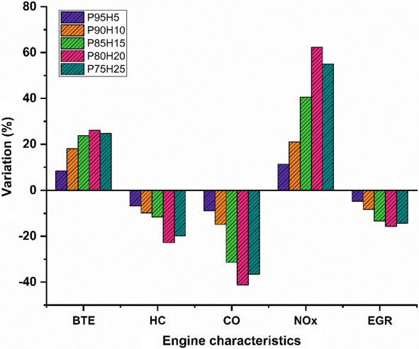
Fig. 10.9 Bar graph depicting overall results and discussions
Instead of hydrogen different gases like LNG and CNG can be used.
Abbreviations
P100 | Pure petrol fuel |
P95H5 | 95% petrol fuel + 5% of hydrogen |
P90H10 | 90% petrol fuel + 10% of hydrogen |
P85H15 | 85% petrol fuel + 15% of hydrogen |
P80H20 | 80% petrol fuel + 20% of hydrogen |
P75H25 | 75% petrol fuel + 25% of hydrogen |
EGT | Exhaust Gas Recirculation |
BTE | Brake Thermal Efficiency |
HC | Hydrocarbon |
CO | Carbon monoxide |
NOx | Oxides of Nitrogen |
ID | Ignition Delay |
BMEP | Brake Mean Effective Pressure |
LHV | Lower Heating Value |
NC | No Change |
PFI | Port Fuel Injection |
H2 | Hydrogen |
DI | Direct Igntion |
SI | Spark Ignition |
References
Brayek M, Jemni MA, Driss Z, Kantchev G, Abid MS (2019) Study of spark-ignition engine fueled with hydrogen produced by the reaction between aluminum and water in presence of KOH. Arab J Sci Eng 44(2):695–705. https://doi.org/10.1007/s13369-018-3192-4
Changwei J, Wang S (2009) Effect of hydrogen addition on combustion and emissions performance of a spark ignition petrol engine at lean conditions. Int J Hydrog Energy 34:7823–7834. (Science direct, Elsevier)
Changwei J, Wang S, Zhangn B (2010) Combustion and emissions characteristics of a hybrid Hydrogen petrol engine under various loads and lean conditions. Int J Hydrog Energy 35(11):5714–5722. (Science direct, Elsevier)
Das LM (2007) Hydrogen engine: research and development (R&D) programmes in Indian institute of technology (IIT), Delhi. Int J Hydrog Energy 27(9):953–965. (Science direct, Elsevier)
Dash SK, Lingfa P, Barik D (2020) Combined adjustment of injection timing and compression ratio for an agricultural diesel engine fuelled with Nahar methyl ester. Int J Ambient Energy 1–13. https://doi.org/10.1080/01430750.2020.1712250
Edmondson H, Heap MP (1971) The burning velocity of hydrogen-air flames. Combust Flame 16:161–165
Elkelawy M, Bastawissi HA-E (2013) Numerical study on the hydrogen fueled SI engine combustion optimization through a combined operation of DI and PFI strategies. Energy Power Eng 05(08):513–522. https://doi.org/10.4236/epe.2013.58056
Elumalai PV, Parthasarathy M, Hariharan V (2021) Evaluation of water emulsion in biodiesel for engine performance and emission characteristics. J Therm Anal Calorim. https://doi.org/10.1007/ s10973-021-10825-z
Ji C, Wang S (2009) Effect of hydrogen addition on the idle performance of a spark ignited petrol engine at stoichiometric condition. Int J Hydrogen Energy 34(8):3546–3556. https://doi.org/10. 1016/j.ijhydene.2009.02.052
Karim G (2003) Hydrogen as a spark ignition engine fuel. Int J Hydrogen Energy 28:569–577. https://doi.org/10.2298/HEMIND0206256K
Li H, Karim GA (2006) Hydrogen fueled spark-ignition engines predictive and experimental performance. J Eng Gas Turbines Power 128(1):230–236. https://doi.org/10.1115/1.2055987. Karim
Masood M, Mehdi SN, Ram Reddy P (2007) Experimental investigations on a hydrogen-diesel dual fuel engine at different compression ratios. J Eng Gas Turbines Power 129(2):572
Murugesan P et al. (2017) Role of hydrogen in improving performance and emission characteristics of homogeneous charge compression ignition engine fueled with graphite oxide nanoparticleadded microalgae biodiesel/diesel blends. Int J Hydrog Energy. https://doi.org/10.1016/j.ijh ydene.2021.08.107
Navale SJ, Kulkarni RR, Thipse SS (2017) An experimental study on performance, emission and combustion parameters of hydrogen fueled spark ignition engine with the timed manifold injection system. Int J Hydrogen Energy 42(12):8299–8309. https://doi.org/10.1016/j.ijhydene.2017. 01.059
Negurescu N, Pana C, Cernat S (2012) Aspects of using hydrogen in SI engine. UPB Sci Bull Ser D Mech Eng 74(1):11–20
Perumal Venkatesan E, Balasubramanian D, Samuel OD, Kaisan MU, Murugesan P (2021) Effect of hybrid nanoparticle on DI diesel engine performance, combustion, and emission studies. In: Singh AP, Agarwal AK (eds) Novel internal combustion engine technologies for performance improvement and emission reduction. Energy, environment, and sustainability. Springer, Singapore. https://doi.org/10.1007/978-981-16-1582-5_10
Rahaman MM, Mohammed K, Rosli AB (2009) Effect of air fuel ratio and engine speed on performance of hydrogen fuelled port engine. Proc Int Multi Conf Eng Comput Sci 2:18–20
Sandalcı T, Karagoz Y (2017) Experimental investigation of the combustion characteristics, emissions and performance of hydrogen port fuel injection in a diesel engine. Int J Hydrogen Energy 39(32):18480e9
Saravanan N, Nagarajan G (2009a) Experimental investigation in optimizing the hydrogen engine fuel on a hydrogen diesel dual-fuel engine. Energy Fuels 23(5):2646e57
Saravanan N, Nagarajan G (2009b). An experimental investigation on manifold-injected hydrogen engine as a dual fuel for diesel engine system with different injection duration. Int J Energy Res 33(15):1352e66
Saravanan N, Nagarajan G, Dhanasekaran C, Kalaiselvan KM (2007) Experimental investigation of hydrogen port fuel injection in DI diesel engine. Int J Hydrogen Energy 32(16):4071e80
SatyapalS(2017)Hydrogen:aclean,flexibleenergycarrier.Officeofenergyefficiency&renewable energy. https://www.energy.gov/eere/articles/hydrogen-clean-flexible-energy-carrier
ShivaprasadKV,RavitejaS,ChitragarP,KumarN(2014)Experimentalinvestigationoftheeffectof hydrogen addition on combustion performance and emissions characteristics of a spark ignition high speed petrol engine. Procedia Technol 14:141–148. https://doi.org/10.1016/j.protcy.2014. 08.019
Shivaprasad KV (2018) Usage of hydrogen as a fuel in spark ignition engine. In: IOP conference series: materials science and engineering, vol 376. IOP Publishing, p 012037. https://doi.org/10. 1088/1757-899X/376/1/012037
Soberanis ME, Fernandez AM (2010) A review on the technical adaptations for internal combustion engines to operate with gas/hydrogen mixtures. Int J Hydrog Energy 35(21):12134–12140. (Science direct, Elsevier)
Verhelst S, Wallner T (2009) Hydrogen fuelled internal combustion engines-review. Int J Prog Energy Combust Sci 35(6); 490–527. (Science direct, Elsevier)
VerhelstS,VerstraetenST,SierensR(2006)CombustionstrategiesandNOxemissionsforhydrogen fueled IC engines. FISITA World Automotive Congress, YOKOHAMA (paper F2006092)
White CM, Steeper RR, Lutz AE (2006) The hydrogen fuelled internal combustion engine: a technical review. Int J Hydrog Energy 31(10):1292–1305. (Science direct, Elsevier)
Yu X, Du Y, Sun P, Liu L, Wu H, Zuo X (2017) Effects of hydrogen direct injection strategy on characteristicsof lean-burn hydrogen–petrol engines. Fuel 208:602–611. https://doi.org/10.1016/ j.fuel.2017.07.059
Hydrogen in Spark Ignition Engines
P. V. Elumalai , N. S. Senthur, M. Parthasarathy , S. K. Das , Olusegun D. Samuel , M. Sreenivasa Reddy , A. Saravana , S. Anjanidevi , Adduri SSM Sitaramamurty , M. Anusha , and Selçuk Sarıkoç
Abstract In the present world, there is a huge demand for sparkignition (SI)engines in transportation sector as there is an increase in population of light commercial vehicles such as motorcycles and cars. Petrol powered SI engine produces less noise and vibration with hight hermal efficiency as compared with diesel engines. Utilization of hydrogen as fuel in SI engines has found to improve the combustion and performance characteristics of engines. The primary fuel petrol and secondary fuel hydrogen are induced in the inlet manifold. The various percentage of hydrogen used in the SI engines include 5, 10, 15, 20 and 25%, together with different ratios of petrol fuel. Whenever hydrogen induced in the SI or compression ignition (CI) engines for safety purpose a flame arrester is used. This current was assessed to calculate the combustion, performance and emission characteristics of a high-speed single cylinder SI engine operating with different hydrogen–petrol blends. The various percentage of hydrogen was inducted along with petrol fuel to reduce the tailpipe emissions. The hydrogen was mixed with base fuels such as P95H5 (95% petrol, 5% of hydrogen),
P. V. Elumalai (B) · S. K. Das · M. Sreenivasa Reddy · A. Saravana · S. Anjanidevi ·
A. SSM Sitaramamurty · M. Anusha
Department of Mechanical Engineering, Aditya Engineering College, Surampalem, India e-mail: elumalai@aec.edu.in
N. S. Senthur
Department of Mechanical Engineering, Bharath Institute of Higher Education and Research, Chennai, India
M. Parthasarathy
Department of Mechanical Engineering, Vel Tech Rangarajan Dr. Sagunthala R&D Institute of Science and Technology, Chennai, India
O. D. Samuel
Department of Mec Hanical Engineering, Federal University of Petroleum Resources, P.M.B 1221, Effurun, Delta State, Nigeria
Department of Mechanical Engineering, Science Campus, University of South Africa, Private Bag
X6, Florida 1709, South Africa
S. Sarıkoç
Department of Motor Vehicles and Transportation Technologies, Amasya University, Tasova Yuksel Akin Vocational School, Amasya, Turkey
© The Author(s), under exclusive license to Springer Nature Singapore Pte Ltd. 2022 195
G. Di Blasio et al. (eds.), Application of Clean Fuels in Combustion Hydrogen Engine, Energy, Environment, and Sustainability, https://doi.org/10.1007/978-981-16-8751-8_10
P90H10 (90% petrol, 10% of hydrogen), P85H15 (85% petrol, 15% of hydrogen engine), P80H20(80%petrol,20%ofhydrogen)andP75H25(75%petrol,25%ofhydrogen). About 20% of hydrogen blend showed greater brake thermal efficiency of 26.8% when compared with base fuel. Furthermore, 25% of hydrogen mixed with petrol drastically reduced the hydrocarbon content, carbon monoxide content and exhaust gas temperature petrol by 22.8%, 40.26% and 15.61%, respectively, when compared with base fuel at full load condition.
Keywords Hydrogen · Petrol · Hydrocarbon · Brake thermal efficiency ·
Carbonmonoxide
10.1 Introduction
The fossil fuel powered industries are under immense pressure to meet the required strict emission targets. Fossil fuel shortages and environmental pollution demand some cleaner and sustainable fuel that can dominate both the power and internal combustion engine industry (Brayek et al. 2019). Hydrogen and fuel cells have the potential to minimise greenhouse gas emissions in a variety of applications due to their high efficiency and near-zero emission operations. According to a study financed by the Energy Department, hydrogen has the potential to reduce emissions in the following ways: (a) in light-duty highway vehicles, emission reduction is more than 50% to 90%, compared with today’s petrol vehicles; and (b) in specialty vehicles, emissions are reduced by more than 35%, compared with contemporary diesel and battery-powered lift trucks; and (c) transit buses have shown to be 1.5 times more fuel efficient than diesel fuelled internal combustion engine buses and 2 times more efficient than natural gas powered buses. Auxiliary power units (APUs) reduce pollutants by more than 60% when compared with idling truck engines. Combined heat and power (CHP) systems reduce emissions by 35–50% when compared with traditional heat and power sources (Changwei and Wang 2009). The most difficult aspect of producing hydrogen, especially from renewable sources mainly depends on the investment. On a per-mile basis, hydrogen must be cost-competitive with conventional fuels and technology for use as transportation fuel cells. Another challenge is the storage of hydrogen as it is highly flammable. Apart from being a clean burning fuel having superior physico-chemical properties, hydrogen has already established its space in energy sector (Changwei et al. 2010). Hydrogen can be produced from a range of local sources, including natural gas, nuclear power, biomass, and renewable energy sources such as solar and wind power. These characteristics make it a desirable fuel for transportation and electricity generation. It can be readily utilized in automobiles, homes, portable powers, and a variety of other applications. Natural gas is now the most common source of hydrogen generation, accounting for roughly three-quarters of the total dedicated hydrogen production of around 70 million tons per year. This accounts for around 6% of global natural gas consumption (Das 2007). In comparison to typical fossil fuels like petrol, diesel, and natural gas, hydrogen has a wider range of combustion parameters like faster diffusion rate and flame propagation (Dash et al. 2020). Hydrogen also possesses quite low ignition energy. Because of a variety of factors, hydrogen has recently gained momentum as a viable energy resource for upcoming generation of automotive. In addition to hydrogen atoms, all common fossil fuels contain carbon atoms and moreover carbon dioxide (CO2) is a major product generated during the conversion of the fuel to energy. The hydrogen releases just water as a by-product but not CO2 which is a major greenhouse gas. However, pure hydrogen suffers storing issues which can be addressed by blending with other liquid fuels. Production, storage, portability, transport, and purity are the main drawbacks that prevent hydrogen from becoming a widely used engine fuel (Edmondson and Heap 1971). Over a wide spectrum of air–fuel ratio, hydrogen can be utilized in IC engines. Over many decades, several researchers have attempted to use hydrogen as an engine fuel with varying levels of success. Several successful projects have proved that hydrogen is far superior to present automotive fuels in many ways. Elkelawy and Bastawissi 2013 studied the inclusion of hydrogen to a petrol powered spark ignition engine at various operating regime. They observed that the engine’s idle speed is roughly maintained around its initial objective as hydrogen enrichment levels rise, while spark timing varies somewhat with and without hydrogen addition. With hydrogen, however, the intake air flow reduces. The SI engine with hydrogen enrichment has a higher indicated thermal efficiency. The periods of flame generation and propagation, as well as COVimep, decrease as the proportion of hydrogen infusion is increased. They also reasoned that with the decreased in-cylinder temperature and increased residual gas percentage, NOx emission reduces as hydrogen enrichment increases. CO and HC emissions initially fall with the addition of hydrogen but when the hydrogen energy share hits 14.44% the emission begin to rise again. Shivaprasad et al. (2014) experimentally studied the performance of a high speed Lombardini make 9 kW@4400 rpm petrol engine with the inclusion of hydrogen share from 0–25 vol.%. Hydrogen addition resulted in improved brake mean effective pressure. Furthermore, 20% hydrogen inclusion results in maximum BMEP at engine speed of 3000 rpm. They also witnessed a rise in BTE up to 20% hydrogen share. By hydrogen enrichment, reduction in CO and HC emission is seen, whereas, rise in NOx emission is also seen. Elumalai et al. 2021 observed that for direct injection hydrogen powered SI engine the performance is improved at partial loads. Technically, no CO2 emission is reported and minor HC and CO forms as a result of engine oil burning inside the cylinder, however, NOx emission increased considerably for λ value of 1 to 2 (9). Studied the performance of a four cylinder water cooled engine powered by mixture of petrol and hydrogen, where hydrogen is added by direct injection. They employed unique lean burn technology for the engine trial. The oxygen content in the combustion system is increased due to the lean burn. Additionally, hydrogen has a faster flame propagation rate, which may aid in CO oxidation. After infusing 10% share of hydrogen, the mean effective pressure and thermal efficiency are enhanced by 10% and 4–4.5%, respectively.Althoughleanburncanenhancethermalefficiencyandreducethrottling loss, it increases COV and HC emissions. With an acceptable injection technique and lean burn circumstances, the COV can be lowered to below 1% and HC emission can be identical to the standard objective level. The inclusion of hydrogen raises the peak cylinder warmth, resulting in a considerable rise in NOx emissions; however, using lean-burn technology, NOx can be dramatically reduced while power and fuel efficiency can be significantly improved. Ji and Wang 2009 studied the hydrogen powered SI engine characteristics with ECU operated time-based manifold injection system. All experiments are conducted at speeds ranging from 1100 to 1800 rpm. For comparison purposes, baseline observations are made with petrol. In the event of hydrogen operation, maximum braking power is reduced by 19.06%, while peak brake thermal efficiency is raised by 3.16%. They reasoned that due to lower volumetric efficiency of hydrogen, the brake power is lowered. Karim 2003 have made numerical investigation to optimize the various injection strategies, such as port fuel injection (PFI), direct injection (DI) and combination of PFI + DI, on the hydrogen fuelled SI engine characteristics. At wide-open throttle, the suggested hybrid techniquecansatisfylowandhighloadsituationswithoutanomalouscombustion.Atlow and high load areas, the hybrid approach of PFI + DI has higher suggested thermal efficiency and engine operation consistency than port fuel injection and in-cylinder direct injection, respectively. From the literatures, it was observed that limited works have been reported on hydrogen powered SI engine. Moreover, some results are also contradictory with respect to NOx and HC emissions. In this backdrop, much quality based work needed to be done on hydrogen powered SI engines in order to draw some strong conclusions and plan future prospects.
In Table 10.1 two symbols are used the upward triangle shows an increase and downward triangle shows a decrease. NC means no change.
Table 10.1 Performance and emissions characteristics of SI engines fuelled by hydrogen
|
H2 Supply |
Load (%) |
Performance |
Emission Characteristics |
References |
||||
|
BSFC |
BTE |
CO |
NOx |
HC |
PM/Smoke |
|||
|
9.4–37% |
25–100 |
NC |
▲ |
▼ |
▼ |
▲ |
▼ |
Li and Karim (2006) |
|
9.4–37% |
50–75 |
NC |
▲ |
▼ |
▲ |
▲ |
▼ |
|
|
2–9.5 lpm |
25 |
NC |
▲ |
NC |
▼ |
▼ |
▼ |
Masood et al. (2007) |
|
2–9.5 lpm |
50–75 |
NC |
▲ |
▲ |
▲ |
▲ |
▼ |
|
|
2–9.5 lpm |
100 |
NC |
▲ |
▲ |
▼ |
▼ |
▼ |
|
|
10–40% |
10 |
▲ |
▼ |
▼ |
▼ |
▼ |
▼ |
Murugesan P et al. (2017) |
|
10–40% |
30 |
▲ |
▼ |
▼ |
▼ |
▼ |
▼ |
|
|
10–40% |
50 |
▼ |
▲ |
▼ |
▼ |
NC |
▼ |
|
|
10–40% |
70–90 |
▼ |
▲ |
▼ |
▼ |
▼ |
▼ |
|
|
0–46% |
100 |
▲ |
▲ |
▼ |
▲ |
▲ |
▼ |
Navale et al. (2017) |
|
10–100% |
20–100 |
▼ |
▲ |
▼ |
▲ |
▼ |
▼ |
Negurescu et al. (2012) |
|
0–38.6% |
100 |
▲ |
▲ |
▲ |
▼ |
NC |
– |
Perumal Venkatesan et al. (2021) |
Table 10.2 Comparison of properties of various gases versus hydrogen
|
Properties |
Methane |
Propane |
Octane |
Methanol |
Hydrogen |
|
Density (kg/m3) |
0.656 |
2.009 |
780 |
793 |
0.083 |
|
LHV (MJ/kg) |
50 |
45.6 |
47.9 |
22.4 |
120 |
|
Viscosity (10–5 Pas) |
1.03 |
0.43 |
0.53 |
0.61 |
0.84 |
|
Stoichiometric ratio |
17.2 |
15.6 |
14.7 |
6.5 |
34.3 |
|
Combustible range (%) |
5–15 |
2.1–9.5 |
0.95–6 |
6.7–36 |
4–75 |
|
Adiabatic flame temperature (°C) |
1949 |
1980 |
1927 |
1963 |
2254 |
|
Ignition energy (mJ) |
0.30 |
0.30 |
0.26 |
0.14 |
0.017 |
|
Ignition temp (°C) |
540–630 |
450 |
415 |
460 |
585 |
10.2 Materials and Methods
10.2.1 Hydrogen
Hydrogen is a clean-burning fuel when compared with other types of alternative fuels like biofuel, CNG, LPG, and biodiesel. There are various methods to produce hydrogen gas such as steam reforming and electrolysis of water. Now-a-days, many application sectors use hydrogen as an energy source (Rahaman et al. 2009). The use of hydrogen in IC engines is a very lesser quantity because of safety and handling issues. There are many benefits when hydrogen is used as a fuel in an IC engine, the results were obtained have more advantages than conventional fuels inclusive of lesser noise, lower vibration, greater efficiency, and cutdown the emission. Hydrogen is the only gas having greater octane (>130) when compared with other types of gases. Hydrogen has the only demerit of storage and handling when used in an IC engine. And also, a very much less quantity of hydrogen can only be used in the combustion process of an IC engine (Sandalcı and Karagoz 2017). Table 10.2 shows the comparison of properties of various gases versus hydrogen.
10.2.2 Fuel Preparation
The present investigation was analyzed in SI engine powered by hydrogen blend petrol. From the study, primary fuel is used as petrol and secondary fuel is hydrogen. The hydrogen mixed with base fuel was prepared the fuel blend of P95H5 (95% g Petrol, 5% hydrogen), P90H10 (90% petrol, 10% hydrogen), P85H15 (85% g Petrol, 15% hydrogen), P80H20 (80% g Petrol, 20% hydrogen), and P75H25 (75% g Petrol, 25% hydrogen) as shown in Fig. 10.1.
 Fig. 10.1 Flowchart depicting concentration of fuel used in analysis
10.3 Experimental Setup
The experiment was carried on single cylinder PRODIT petrol engine. Table 10.1 provides details of engine. The research lab consisted of test rig including an eddy current-type dynamometer, exhaust gas analyzer, petrol metering device as well as other auxiliary equipment (Saravanan and Nagarajan 2009a). A diagrammatic representation of the test rig is given in Fig. 10.2. A 50 kg hydrogen cylinder was used to supply hydrogen in the intake manifold. Cylinder contains compressed hydrogen at 200 bar. The hydrogen stream regulate framework had been fitted at the upper corner of the hydrogen cylinder that consisted of hydrogen controller as well as the hydrogen flow pointer. The hydrogen control process controls the hydrogen stream supplied to the engine as well as the quantity of hydrogen stream could be defined by hydrogen stream pointer(ChangweiandWang2009).The petrol engine was modified for utilizing hydrogen along with gasoline. The flame trap placed was placed in the middle of the hydrogen cylinder and engine which is used to suppress the back fire in
Fig.10.3.Thepreparedelectroniccontrollerwasconnectedwiththedataprocessorto
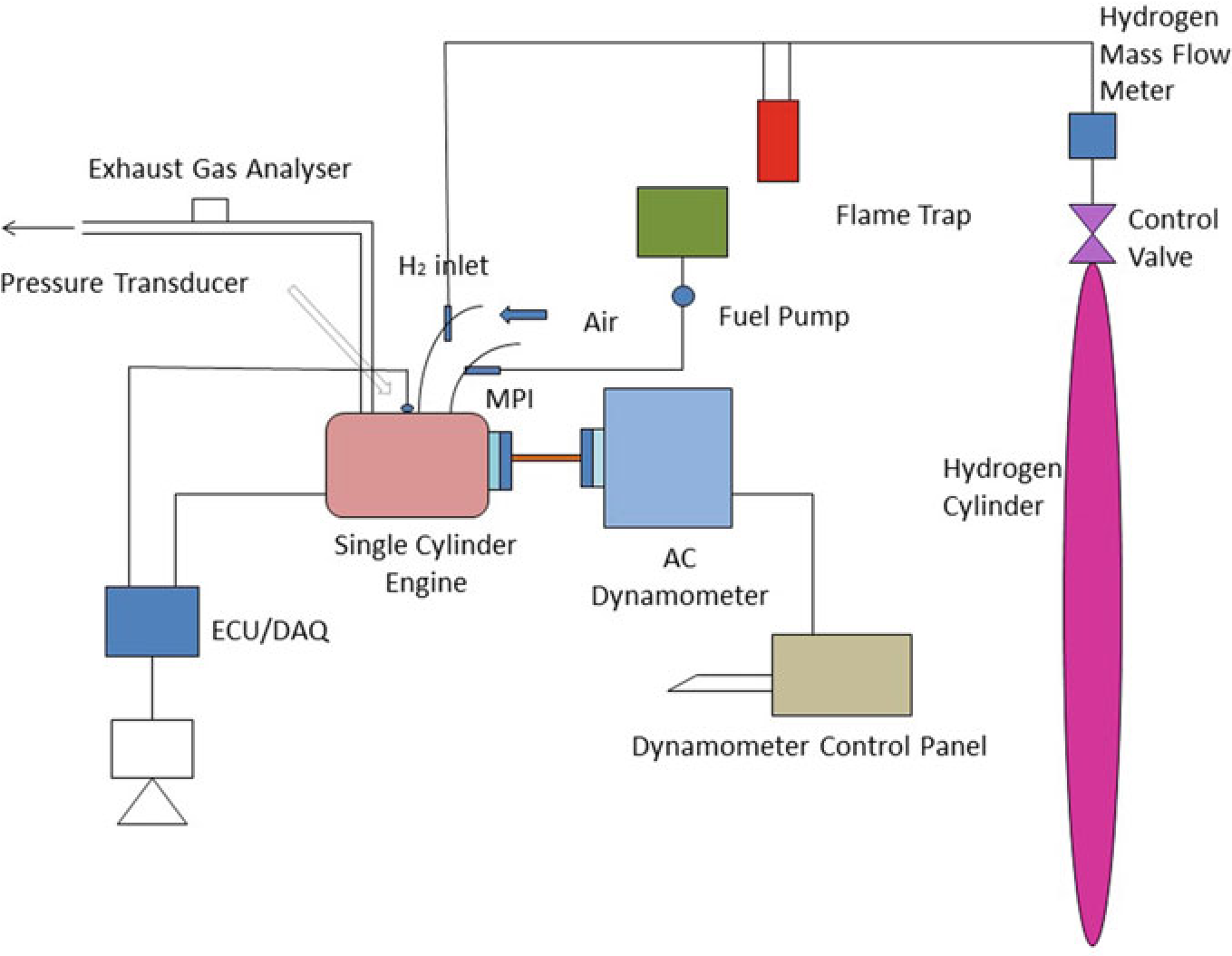
Fig. 10.2 Experimental setup
the RS-232 port. The exhaust release from the test engine had been assessed utilizing exhaust gas analysis apparatus that was located at exhaust system. An assessment of sensor performance, including ranges, cross sensitivity, reliability, durability, and expense are made. As hydrogen leakage are probable, hydrogen sensors are installed at hydrogen connectors that are regularly isolated, where hydrogen may concentrate in buildings air inlet and outflow pipes. While developing a hydrogen detection technique, aspects such as sensor reaction times, detection limit, sensor serviceability, sensor maintenance and calibration needed, issues arising due to sensitivity, and field of view should be considered. Special attention must be paid to the identification of hydrogen leaks and hydrogen flame in hydrogen test cells. Apart from detecting gaseous hydrogen to ensure a safe test cell atmosphere, hydrogen leakage should also be monitored as leakage could easily produce flames without warning. Especially, a hydrogen leakage would not be easily detected using a gaseous hydrogen monitoring device until it leads to ignition. The experiment assessed at engine speeds of 2000–4000 rpm by incrementing the speed around 500 rpm. Using a controller, the various mass fraction of hydrogen (5, 10, 15, 20, and 25%) was inducted along with base fuel. The present study intended to analyze the operation as well as release of toxic gas attributes in a high velocity SI engine that had utilized hydrogen enhanced besides ECU regulated MPI system. Table 10.3 shows that specification of engine.
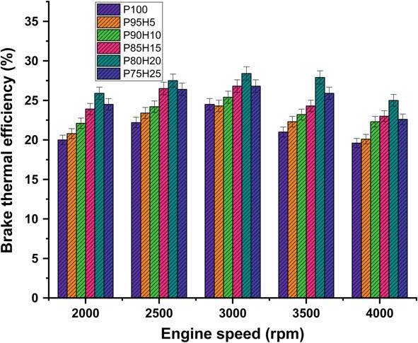
Fig. 10.3 Graph depicting speed versus BTE
Table 10.3 Engine specification
|
Engine model |
PRODIT Gpetrol engine |
|
Bore (mm) |
90 |
|
Stroke (mm) |
85 |
|
Compression ratio |
9.6 |
|
Maximum torque |
23 Nm |
|
Maximum power |
11 kW |
|
Ignition timing |
9.10 CA before TDC |
|
Fuel |
Petrol fuel hydrogen |
+
10.3.1 Uncertainty Analysis
The results of the analyses performed using various apparatus largely depend on the standard of the manufacturers. To overcome the drawbacks and to assure standard results using the instruments, uncertainty analyses of various systematic parameters are performed. Errors and uncertainty while using instruments largely depend on various natural conditions, perceptions, assembling of the instruments, working conditions, and also on the accuracy of the instruments. The evaluation tests were performed four times and the average values were taken for the assurance of vulnerability in this work as shown in Table 10.4.
|
S. no |
Parameters |
Systematic errors (±) |
|
1 |
Load indicator |
0.2 |
|
2 |
Speed sensor |
1.0 |
|
3 |
Temperature sensor |
0.1 |
|
4 |
Pressure sensor |
0.5 |
|
5 |
Crank angle encoder |
0.2 |
|
6 |
Smoke meter |
1.0 |
|
8 |
Fuel burette |
1.0 |
|
9 |
Manometer |
1.0 |
Table 10.4 Uncertainty analysis
![]() [uncertaintyofload]2+[uncertaintyof speed]2+[uncertaintyof Temp]2+ [uncertaintyof unburntPressure]2+[uncertaintyof CA]2+
[uncertaintyofload]2+[uncertaintyof speed]2+[uncertaintyof Temp]2+ [uncertaintyof unburntPressure]2+[uncertaintyof CA]2+
![]() [uncertaintyof smoke]2+[uncertaintyof f uel]2+
[uncertaintyof smoke]2+[uncertaintyof f uel]2+
[uncertaintyof manometer]2

= 2.21%
10.4 Results and Discussion
The two fuels used in the SI engine include the primary fuel petrol and the secondary fuel hydrogen. The hydrogen mixed with base fuels were P95H5 (95% petrol, 5% hydrogen), P90H10 (90% petrol, 10% hydrogen), P85H15 (85% petrol, 15% hydrogen), P80H20 (80% petrol, 20% hydrogen), and P75H25 (75% petrol, 25% hydrogen). The various concentrations of hydrogen and petrol fuels filled with SI engine were found performance and emission characteristics.
10.4.1 Brake Thermal Efficiency of the hydrogen engine
Figure 10.3 expose the variations of brake thermal efficiency (BTE) and different speed conditions of SI hydrogen engine. The BTE evaluates the performance of the engine. The induction rate of hydrogen was increased with increase in the BTE of engine for all load conditions petrol was clearly observed that the highest BTE was 26.05% for P80H20 at speed 3500 rpm. It might be due to premixed charge of hydrogen and petrol and high energy density of hydrogen which exhibits better oxidation process (Saravanan and Nagarajan 2009b). The BTE of P95H5, P90H10, P85H15, P80H20, and P7525 is 20.1%%, 22.3%, 23.0%, 25.0%, and 22 0.06%, respectively, when compared with 17.6% for without hydrogen induced P100. It could be attributed that the flame speed of hydrogen is three times greater than the petrol and wide range of flammabilityofhydrogenwhichscatteredthroughoutthechambercanbeachievedby complete combustion petrol. The petrol mixture blended with hydrogen showed faster combustion and enriched energy value thus resulting in better combustion efficiency. The results also showed that BTE of 0% hydrogen induction showed lower BTE than other test fuel condition due to energy value of petrol premixed charge was lower than hydrogen premixed charge. Moreover, 20% hydrogen enrichment was exhibited 14.4, 10.5, 5.6 and 5.4% higher BTE P95H5, P90H10, P85H15 and P75H25 at rated speed condition. Addition of hydrogen above 20% to the petrol fuel showed decrease in BTE, due to the irregular flame propagation and start of combustion which leads to notice the unstable engine operation. Saravanan et al. 2007 as the fraction of hydrogen added increases accumulation of hydrogen increases in the cylinder which results in a decrease in the amount of air required for complete combustion. For these reason, the 25% hydrogen enrichment fuel was found to have low thermal efficiency (Satyapal 2017).
10.4.2 Brake Mean Effective Pressure in the hydrogen engin
Figure 10.4 exhibits the difference of brake mean effective pressure (BMEP) for the hydrogen enrichment petrol in SI hydrogen engine. In Fig. 10.4, it was clearly seen that gradual increase in hydrogen concentration in the fuel mixture gradually increases the BMEP all speed condition. Due to greater value of octane number and wider range of flammable limits found in the hydrogen fuel, the combustion pressure also increases the BMEP. In addition, the hydrogen has faster flame propagation and greater adiabatic temperature when compared with the petrol fuel that are helpful for uniform combustion throughout the chamber. By increasing the hydrogen concentration by 25%, the BMEP was decreased by 4.5% when compared with P80H20. Combination of multi-directional flame propagation and less entry of air into the manifold leads to inferior combustion rate. The P80H20 showed higher value of BMEP when compared with the other test fuels. It might be due to unidirectional flame propagation and less flame quenching zones leading to better combustion rate thereby enhanced BMEP (Shivaprasad et al. 2014).
10.4.3 Carbon Monoxide
Figure 10.5 displays graph depicting the difference in carbon monoxide (CO) with various engine speed condition for petrol enriched hydrogen. Normally, petrol operatedSIengineemitsmoreCOathigherspeedconditionduetopoorairutilizationand fuel rich zone in chamber petrol. The test results showed that a reasonable reduction of CO emission was found in the hydrogen enriched SI engine. It was mainly due to
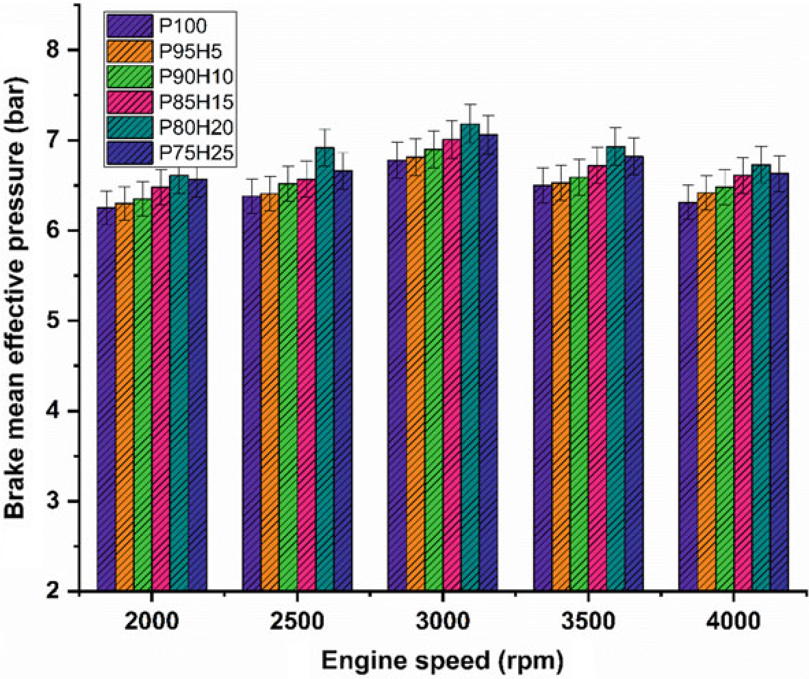
Fig. 10.4 Graph depicting speed versus BMEP
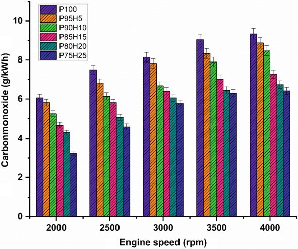
Fig. 10.5 Graph depicting speed versus CO
the absence of carbon atoms in the hydrogen fuel leading to restriction of CO formation (Shivaprasad et al. 2014). When increasing the hydrogen concentration with the petrol, the drastic reduction of CO emission was observed whereas beyond 25% hydrogen enrichment the CO emissions start to increase. This result increases the wall impingement and enhances the ignition lag that results in incomplete combustion. The magnitude of CO emission for the fuels P95H5, P90H10, P85H15, P80H20, and P75H25 were reduced by 8.8%, 14%, 31.3%, 33.5%, and 41.2%, respectively, when comparedwithP100.ItcanbeinferredthatmorechancesforformationofOHradical by hydrogen enrichment can results in better combustion efficiency. Utilization of hydrogen along with petrol leads to positive impact on greater flame velocity, faster combustion rate, and higher stoichiometric air–fuel ratio that results in improve the CO oxidation. The 25% of hydrogen induction showed 26.2%, 13.5%, 9.8% and 4.7% lower CO emission than hydrogen induction of 5, 10, 15, and 20% respectively. The hydrogen produces higher combustion temperature when compared with the petrol which aids to enhance the carbon oxidation. The maximum CO reduction was achieved by 25% of hydrogen induction because of high adiabatic flame temperature and wide flammability which enhance the CO conversion rate into CO2. While increase in the hydrogen induction beyond 25% leads to replacement of air quantity that results in poor air utilization and lower volumetric efficiency therefore reduced CO2 formation.
10.4.4 Hydrocarbon in hydrogen engine
Figure10.6 exhibits the difference in hydrocarbon (HC) emission with respect to variable engine speed for hydrogen enrichment with P100. From the results, it can be seen that petrol powered SI engine produced higher HC emission than hydrogen assisted combustion of petrol. When increasing the hydrogen concentration, the HC emission was drastically reduced at all speed condition. It could be ascribed that addition of hydrogen and formation of OH radial in to the combustion process enhances the oxidation of fuel. The test results also revealed that the premixed charge of hydrogen and petrol were found to minimize HC emission because of high post-combustion temperature and enhanced oxidation reaction which promoted faster combustion rate. The other possibility to reduce the HC emission for hydrogen induction was by lowering the quenching distance and high flame velocity those results in shortening the combustion duration (Shivaprasad 2018).
The shortening of quenching distance and combustion duration helps to burns the fuel completely during combustion which in turn reduces HC formation. The HC emission for P95H5, P90H10, P85H15, P80H20, and P8025 was reduced by 6.7%, 9.8%, 11.6%, 19.7%, and 22.8%, respectively, when compared with the P100. The P100 found highest HC emission of about 224 ppm. It was mainly due to the lesser chemically correct mixture of petrol which enabled more amount of fuel to enter
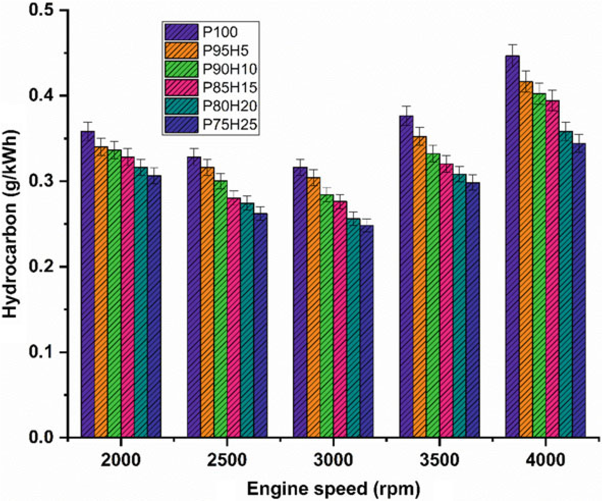
Fig. 10.6 Graph depicting speed versus HC
into the chamber and inferior air utilization also results in HC formation. The 25% of hydrogen induction drastically reduced the HC emission as related to P100. It might be due to high stoichiometric air–fuel mixture of hydrogen (34:1) and high diffusivitywithairthatresultsinmoreairutilizationandpromotetheinitialoxidation of hydrocarbon.
10.4.5 Oxides of Nitrogen (NOx) in the hydrogen engine
The effect of hydrogen enrichment with P100 on formation of NOx emission in SI hydrogen engine is portrayed in Fig. 10.7. Evolution of higher temperature during combustion results in NOx formation in the engine. While increasing the concentration of hydrogen gradually increase the NOx emission in SI engine. It could be attributed to higher heat value of hydrogen dissipate more amount of heat during combustion that aids to promote the nitrogen oxidation (Soberanis and Fernandez 2010). In addition, higher hydrogen induced in to the inlet manifold raises the combustion rate which enhances the post-combustion temperature. The NOx emission for P95H5, P90H10, P85H15, P80H20, and P8025was increased by 11.3%, 21%, 40.6%,55%, and 62.3%, respectively, when compared with P100. The 25% of hydrogen induced in to the base fuel showed the maximum rate of formation of oxides of nitrogen at rated speed

Fig. 10.7 Graph depicting speed versus NOx
condition. This was mainly due to the wide flammability and high cylinder temperature produced during combustion which exhibited more NOx formation (Verhelst and Wallner 2009). The lowest oxides of nitrogen are observed for blend P100 which was18.2%lowerwhencomparedwith25%of hydrogen induced fuel. This result was responsible for lower heating value and less air–fuel ratio of P100 which results in fuel rich zone in cylinder therefore lower combustion temperature (Verhelst et al. 2006).
10.4.6 Exhaust Gas Temperature in the hydrogen engine
The impact of hydrogen enrichment with P100 on exhaust gas temperature (EGT) in SI engine was represented in Fig.10.8. The shorter combustion rate and high cylinder temperature leads to production of higher EGT. It was evident that hydrogen enriched fuel observed higher EGT than normal fuel because of high adiabatic flame temperature of hydrogen which resulted in enhanced post-combustion temperature. EGT for all test fuels was lower under low speed condition. At full speed condition, high rate hydrogen induction with base fuel produced superior EGT than lower rate of hydrogen induction. It was mainly due to more air utilization and better combustion leading to rise in cylinder temperature (White et al. 2006). When increasing the hydrogen concentration linearly the EGT increases for all speed condition. The
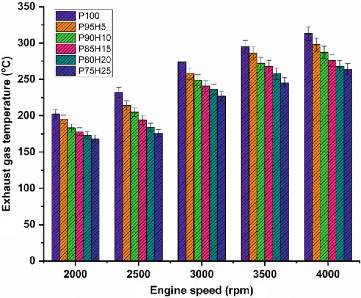
Fig. 10.8 Graph depicting speed versus EGT
highest EGT was observed for 25% of hydrogen induction owing to a higher diffusivity of hydrogen which leads to easily mix the fuel with air thereby increasing the homogenous charge preparation. The EGT of P95H5, P90H10, P85H15, P80H20, and P75H25 was increased by 4.7%, 8.3%, 13.4%, 14.3%, and 15.6%, respectively, when compared with the 0% of hydrogen induction with base fuel. This result showed that the dual effect of higher flame propagation of hydrogen and low quenching distance together improved the combustion rate of the test fuels (Yu et al. 2017).
10.5 Conclusions for the hydrogen engine
In the present study, the P100 inducted along with various percentage of hydrogen through intake manifold to assess the SI engine characteristics. The ultimate aim of this study was to find the optimum percentage of hydrogen induction with P100 for use in SI engines. Based on the experimental results, it was clearly identified that hydrogen enriched P100 showed better performance and lower emission value. The effect of hydrogen enrichment with P100 on SI engine performance and emission parameter was exposed in Fig. 10.9.
- The highest BTE noticed for the fuel P80H20 was about 26.05% at rated speed conditionowingtosuperiorheatingvalueandflamevelocityofhydrogenwhich exhibits better combustion rate.
- While increase the hydrogen enrichment beyond 25%, unstable engine operation and knocking also was observed due to partial replacement of oxygen and poor air utilization rate that resulted in fuel zone in chamber thereby inferior combustion rate.
- The HC and CO emission of P75H25 was reduced by 22.8% and 41.28%, respectively, when compared with base fuel. Due to wider flammability, high flame velocity, and absence of carbon particle in hydrogen fuel which reduce thequenchingdistancetherebyincreasethecylindertemperatureandoxidation rate of CO and HC.
- In contrast, when increasing the hydrogen concentration with P100, NOx emission was linearly increased due to high adiabatic flame temperature of hydrogen and high stoichiometric air–fuel ratio (34:1) leads to consumption of more quantity of air during the combustion thus resulting in high peak cycle temperature.
Scope of Future
The various future scope of the study includes:
- Instead of petrol different fuels like biodiesel, biofuel and so on can be used.

Fig. 10.9 Bar graph depicting overall results and discussions
- Instead of hydrogen different gases like LNG and CNG can be used.
Abbreviations
|
P100 |
Pure petrol fuel |
|
P95H5 |
95% petrol fuel + 5% of hydrogen |
|
P90H10 |
90% petrol fuel + 10% of hydrogen |
|
P85H15 |
85% petrol fuel + 15% of hydrogen |
|
P80H20 |
80% petrol fuel + 20% of hydrogen |
|
P75H25 |
75% petrol fuel + 25% of hydrogen |
|
EGT |
Exhaust Gas Recirculation |
|
BTE |
Brake Thermal Efficiency |
|
HC |
Hydrocarbon |
|
CO |
Carbon monoxide |
|
NOx |
Oxides of Nitrogen |
|
ID |
Ignition Delay |
|
BMEP |
Brake Mean Effective Pressure |
|
LHV |
Lower Heating Value |
|
NC |
No Change |
|
PFI |
Port Fuel Injection |
|
H2 |
Hydrogen |
|
DI |
Direct Igntion |
|
SI |
Spark Ignition |
Declaration of Competing Interest
The authors declare that they have no known competing financial interests or personal relationships that could have appeared to influence the work reported in this paper.
References
Brayek M, Jemni MA, Driss Z, Kantchev G, Abid MS (2019) Study of spark-ignition engine fueled with hydrogen produced by the reaction between aluminum and water in presence of KOH. Arab J Sci Eng 44(2):695–705. https://doi.org/10.1007/s13369-018-3192-4
Changwei J, Wang S (2009) Effect of hydrogen addition on combustion and emissions performance of a spark ignition petrol engine at lean conditions. Int J Hydrog Energy 34:7823–7834. (Science direct, Elsevier)
Changwei J, Wang S, Zhangn B (2010) Combustion and emissions characteristics of a hybrid Hydrogen petrol engine under various loads and lean conditions. Int J Hydrog Energy 35(11):5714–5722. (Science direct, Elsevier)
Das LM (2007) Hydrogen engine: research and development (R&D) programmes in Indian institute of technology (IIT), Delhi. Int J Hydrog Energy 27(9):953–965. (Science direct, Elsevier)
Dash SK, Lingfa P, Barik D (2020) Combined adjustment of injection timing and compression ratio for an agricultural diesel engine fuelled with Nahar methyl ester. Int J Ambient Energy 1–13. https://doi.org/10.1080/01430750.2020.1712250
Edmondson H, Heap MP (1971) The burning velocity of hydrogen-air flames. Combust Flame 16:161–165
Elkelawy M, Bastawissi HA-E (2013) Numerical study on the hydrogen fueled SI engine combustion optimization through a combined operation of DI and PFI strategies. Energy Power Eng 05(08):513–522. https://doi.org/10.4236/epe.2013.58056
Elumalai PV, Parthasarathy M, Hariharan V (2021) Evaluation of water emulsion in biodiesel for engine performance and emission characteristics. J Therm Anal Calorim. https://doi.org/10.1007/ s10973-021-10825-z
https://www.iea.org/reports/the-future-of-hydrogen
Ji C, Wang S (2009) Effect of hydrogen addition on the idle performance of a spark ignited petrol engine at stoichiometric condition. Int J Hydrogen Energy 34(8):3546–3556. https://doi.org/10. 1016/j.ijhydene.2009.02.052
Karim G (2003) Hydrogen as a spark ignition engine fuel. Int J Hydrogen Energy 28:569–577. https://doi.org/10.2298/HEMIND0206256K
Li H, Karim GA (2006) Hydrogen fueled spark-ignition engines predictive and experimental performance. J Eng Gas Turbines Power 128(1):230–236. https://doi.org/10.1115/1.2055987. Karim
Masood M, Mehdi SN, Ram Reddy P (2007) Experimental investigations on a hydrogen-diesel dual fuel engine at different compression ratios. J Eng Gas Turbines Power 129(2):572
Murugesan P et al. (2017) Role of hydrogen in improving performance and emission characteristics of homogeneous charge compression ignition engine fueled with graphite oxide nanoparticleadded microalgae biodiesel/diesel blends. Int J Hydrog Energy. https://doi.org/10.1016/j.ijh ydene.2021.08.107
Navale SJ, Kulkarni RR, Thipse SS (2017) An experimental study on performance, emission and combustion parameters of hydrogen fueled spark ignition engine with the timed manifold injection system. Int J Hydrogen Energy 42(12):8299–8309. https://doi.org/10.1016/j.ijhydene.2017. 01.059
Negurescu N, Pana C, Cernat S (2012) Aspects of using hydrogen engine in SI engine. UPB Sci Bull Ser D Mech Eng 74(1):11–20
Perumal Venkatesan E, Balasubramanian D, Samuel OD, Kaisan MU, Murugesan P (2021) Effect of hybrid nanoparticle on DI diesel engine performance, combustion, and emission studies. In: Singh AP, Agarwal AK (eds) Novel internal combustion engine technologies for performance improvement and emission reduction. Energy, environment, and sustainability. Springer, Singapore. https://doi.org/10.1007/978-981-16-1582-5_10
Rahaman MM, Mohammed K, Rosli AB (2009) Effect of air fuel ratio and engine speed on performance of hydrogen fuelled port engine. Proc Int Multi Conf Eng Comput Sci 2:18–20
Sandalcı T, Karagoz Y (2017) Experimental investigation of the combustion characteristics, emissions and performance of hydrogen port fuel injection in a diesel engine. Int J Hydrogen Energy 39(32):18480e9
Saravanan N, Nagarajan G (2009a) Experimental investigation in optimizing the hydrogen fuel on a hydrogen diesel dual-fuel engine. Energy Fuels 23(5):2646e57
Saravanan N, Nagarajan G (2009b). An experimental investigation on manifold-injected hydrogen as a dual fuel for diesel engine system with different injection duration. Int J Energy Res 33(15):1352e66
Saravanan N, Nagarajan G, Dhanasekaran C, Kalaiselvan KM (2007) Experimental investigation of hydrogen port fuel injection in DI diesel engine. Int J Hydrogen Energy 32(16):4071e80
SatyapalS(2017)Hydrogen:aclean,flexibleenergycarrier.Officeofenergyefficiency&renewable energy. https://www.energy.gov/eere/articles/hydrogen-clean-flexible-energy-carrier
ShivaprasadKV,RavitejaS,ChitragarP,KumarN(2014)Experimentalinvestigationoftheeffectof hydrogen addition on combustion performance and emissions characteristics of a spark ignition high speed petrol engine. Procedia Technol 14:141–148. https://doi.org/10.1016/j.protcy.2014. 08.019
Shivaprasad KV (2018) Usage of hydrogen as a fuel in spark ignition engine. In: IOP conference series: materials science and engineering, vol 376. IOP Publishing, p 012037. https://doi.org/10. 1088/1757-899X/376/1/012037
Soberanis ME, Fernandez AM (2010) A review on the technical adaptations for internal combustion engines to operate with gas/hydrogen mixtures. Int J Hydrog Energy 35(21):12134–12140. (Science direct, Elsevier)
Verhelst S, Wallner T (2009) Hydrogen fuelled internal combustion engines-review. Int J Prog Energy Combust Sci 35(6); 490–527. (Science direct, Elsevier)
VerhelstS,VerstraetenST,SierensR(2006)CombustionstrategiesandNOxemissionsforhydrogen fueled IC engines. FISITA World Automotive Congress, YOKOHAMA (paper F2006092)
White CM, Steeper RR, Lutz AE (2006) The hydrogen fuelled internal combustion hydrogen engine: a technical review. Int J Hydrog Energy 31(10):1292–1305. (Science direct, Elsevier)
Yu X, Du Y, Sun P, Liu L, Wu H, Zuo X (2017) Effects of hydrogen direct injection strategy on characteristicsof lean-burn hydrogen–petrol engines. Fuel 208:602–611. https://doi.org/10.1016/ j.fuel.2017.07.059